Build Lights With Arduino
In the beginning of time (circa. 2013) We had a build light. It’s pretty common, USB attachable, multicoloured, etc. Seems pretty great, right? It was all that we needed for one application, one build.
Then we started building new applications. New applications meant new builds. These builds were originally disparate, running on their own jenkins instances in EC2. How was our one light going to handle the statuses of these different builds?
At the start, we didn’t bother. These new applications weren’t “money-makers”, they weren’t as important as our main monolithic app. But things started to change – the new applications started becoming more important, contributing more meaningfully to the traffic that our main application handles. Now we were starting to feel the pain of not having that direct visual (and audible) notification of whether the build broke… or was good to go.
So why not just add another USB light and be done with it? The USB light we had was attached to a Raspberry Pi B. USB was already limited right there – we had at least 3 builds we wanted to monitor, and could only have two lights (without a hub, at least). The real problem, however, happened to be in identification of multiple lights under our original light control program, which was using libusb in either Python or Ruby (I’m running off second hand info here). From what I was told, they weren’t able to individually address each light.
So… what next?
Fast forward to about September 2014. As geeks are inclined to do, we had acquired a few extra toys. Dan had gotten a couple of Moteinos – Arduino-compatibles built with RF capabilities and a bent towards small form factor and low power. He also had on his hands a 24px Adafruit NeoPixel ring. He’d already got some ideas going in his head, obviously.
We concocted an idea that we would use two moteinos together to create our build light. Our original build light was limited in that it needed to have the raspberry pi to be plugged into. This meant to have multiple lights we’d likely need more than one pi, and even if we could use one pi, all the lights would need to be located nearby (USB cable length requirements, etc). With our moteinos we would use one as a fairly dumb serial-controlled transmitter, while the other was a receiver that controlled the NeoPixel directly. The end effect being a much more advanced, prettier animatable build light. Moreover, we would later be able to add other moteinos into the mix, as the RF units are uniquely addressable.
The (Physical) Build
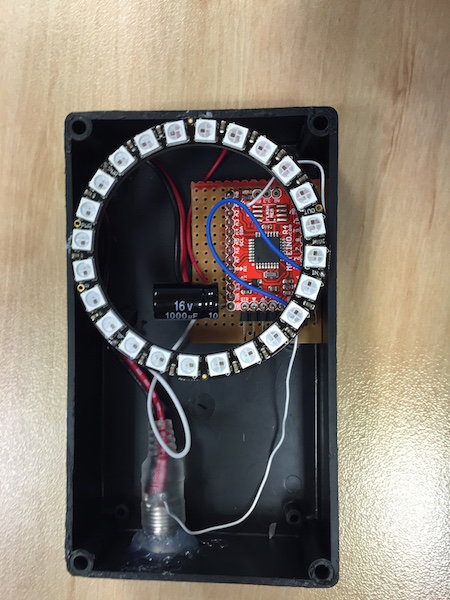
Receiver/Light
Physically, Our build light is pretty simple. The light itself has a pretty small BOM:
- Moteino
- Adafruit NeoPixel Ring 24px
- Capacitor (decoupling/bypass)
- Resistor (data line)
- Power source
“Pretty simple” might be a bit of a misnomer, the Moteino is sorta complex, given it’s rather small and has an RF unit attached to it.
The capacitor was used for decoupling the arduino circuit from the NeoPixel circuit, while the Resistor was used to current-limit the data line going into the NeoPixel ring, much like you might do for a normal LED.
Otherwise, this is pretty simple in my mind. the Moteino and NeoPixel are both connected to the power source, and one of the arduino pins is used to send data to the NeoPixel ring.
One of the cool features of the NeoPixel is they use multi-colour LEDs with integrated drivers that can be chained together, meaning that if you connect the output pin of one to the input pin of another, you connect them together in a connected chain.This is how the ring is built, and they also provide the ability to connect multiple rings together, which would all be controlled by the one pin from the arduino! This means we can take almost all the same code for the 24-LED ring and use it with a 16-LED ring, a 4-LED strip, 144-LED strip, and it’ll all work the same!
Note that I said “almost all the same code”. This is because the number of LEDs in the sequence is required in the code for the initialisation of the ring, as the NeoPixel library is not built to be able to detect the number of LEDs in the sequence.
Transmitter

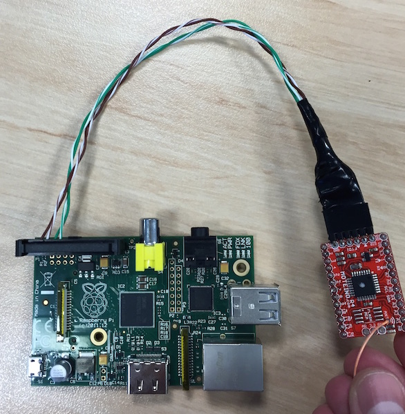
As for the transmitter, All we needed for this was:
- Moteino
- Raspberry Pi B
- 26pin way IDC Line Socket
- 6pin ISP (“stackable”) header
- 4x loose wires
The majority of the parts here of course were to create the custom serial bridge. We used the built in serial port on the Raspberry Pi’s GPIO port. We’re not using it for anything else. Note that this does require some setup to disable in linux.
We could probably have used a USB adapter, but the way we did it requires less interconnects, and didn’t sacrifice an FTDI adapter.
The Code
We have a few different pieces of code running in a few different places. We’ll try to lay them out as simply as possible.
Arduino
The Arduino code is, like the physical build, composed of two different parts – the code that runs on the transmitter, and the code that runs on the receiver. You can find both on github, along with our own wrapper library (LightEffects) around the NeoPixel in the same repository.
The project has always had a defined transmission protocol, or at least an agreed-upon and relatively constant message format. This has not changed at all since the inception of the idea – We nutted out what we thought we would need, we decided upon it, and it hasn’t changed since. This format is the following:
- (8bit int) Function ID – numerical ID for an enumerated function on the receiver side. These IDs are defined in LightEffects.h. They are also defined in transmitter.ino, however I do not believe they are used at all, and are more for reference. They could just be comments in the code for the transmitter.
- (8bit int) Red – desired intensity of red light to be emitted. This goes from 0x00 (off) to 0xFF (full power).
- (8bit int) Green – desired intensity of green light to be emitted. This goes from 0x00 (off) to 0xFF (full power).
- (8bit int) Blue – desired intensity of blue light to be emitted. This goes from 0x00 (off) to 0xFF (full power).
- (8bit int) Iteration delay – This is the delay between changes to the light during a given animation. For instance, during a colour wipe this delay is the amount of time before the next LED/pixel changes in the sequence. This delay is in milliseconds, and has a maximum value of 255ms.
Transmitter code
The transmitter is fairly dumb. About the smartest thing it does is pretty new, and that is parsing numbers in a given input string. All it needs to do is take a given input string and a message of the above format and send it to a node.
First iteration
The first version of the transmitter would take commands over Serial in the format of, for example, xbr. This would generate a payload of 0x0180000032, or, function number 1, 50% red, 0% green, 0% blue, 50ms wait. Breaking this down:
x– Code path the command would flow down (ie that this input would result in something being sent via the radio).[a-z]– Function ID. The Arduino reads the single character as a byte, and subtracts'a'from it. This leaves us with a byte value offset from a, wherea==0x00, which is theNOOPfunction (‘do nothing’).'b', Then, is0x01, or the ‘colour wipe’ function.[rgb]?– optional colour argument.rwas hard coded to 50% red, 0% green, 0% blue.gwas hard coded to 0% red, 50% green, 0% blue.bwas hard coded to 0% red, 0% green, 50% blue. And omitting the value was hard coded to 50% red, 50% green, 0% blue.. AKA yellow.
NB: Why are these values only 50%? 50% is representative of the amount of light output by the LED. Since we only have 3 colours of vaying intensity per channel, we have to define colour as intensity per channel. In interest of not burning all viewer’s retinae, We opted not to use full brightness on any one channel.
The final component, the timing, was hard coded to 0x32 in this original instruction set.
Second iteration
The second iteration of the transmitter is relatively new, and required (almost) no changes on the receiver side. In fact, in terms of correctness of the transmitter, no changes were required – the same message format is used as the first iteration. The only thing that changed is the introduction of a new instruction set.
The new instructions were born of me wanting to give more flexibility to the transmitter to define exactly what function was to be sent. After all, what was the point in send full 24-bit colour data over the radio if only 4 different settings were ever being used?
The new instructions would look like this: s01b#7F403Ct25. The format, broken down, is as follows:
s– Code path choice, much likexin the previous instructions.[0-9A-Fa-f]{2}– 2 hexadecimal digits, representing which node to send the message to. With this one addition, we were now able to send a light change to any light on our “network”![a-z]– function ID. This is the same as the second character in the original instruction set.(#[0-9A-Fa-f]{6})?– pound symbol followed by 6 hexadecimal digits, denoting the colour to send in the message. This is optional, though the omission leads to 0x000000 being sent – in otherwords, no colour.(t[0-9]+)?– t followed by up to three decimal digits, max 255, denoting millisecond wait period between iterations.
Hopefully it’s pretty obvious how this translates into the message format used for transmission. Besides being able to describe the exact “colour” desired, the awesome new additions are being able to tell which node to send the message to, and being able to control timing!
Well, mostly being able to control timing. Unfortunately, because the original instruction set did not actually define a timing, the receiver didn’t use the timing described by the transmission message – whoops! This had to be changed, obviously, in the receiver…
Receiver code
First iteration
The receiver is split into a couple of parts – obviously, the first part is the Arduino code, but moreover, it’s the code written in the Arduino/Wiring language. What’s the other part then? What’s remaining are the light display functions, which control the NeoPixel strip. In my experience with Arduinos, most programs exist in one file, an .ino file, which can get pretty big. I mostly split out the light display code for modularity, so that the .ino file didn’t get unweildly.
For the most part, the Arduino code of the first iteration deals with initialising globals (“ewww!” scream the high-level language purists), starting up the radio and then sending any radio packets through to the light code. Every loop iteration, the radio is checked for any new data. If data is found, it is stored in a buffer and sent to the light code, along with a true reset flag. If no data is found, the last captured data is taken from the buffer and sent to the light code, with a false reset flag. Note that we are actually passing the iteration delay into the light code.
The light code is where things probably start getting interesting. Not because of the outcome – we prety much stole the effects from the strandtest.ino file that comes with the Adafruit_NeoPixel library. What we did have to do, however, was change the way the effects were being run. As they were, straight out of srandtest.ino, you would call the light functions and then have to wait for the function to complete. This wouldn’t do – we could receive a signal from our radio at any time! We needed interruptable display functions.
For the first iteration, this “interruptability” was acheived for only a couple of functions, and was done with (yet more) global(s) and unwrapping the heart of the functions from their encasing for() loops. The reset flag when calling into the light code literally just set the iteration global to 0.
There wasn’t much encapsulation going on this first time around, the entrypoint into the light code was a single runFunc function, though you could still access the rest of the functions (which now only did a single step of the given performance) if you really wanted to. (You didn’t.)
Second iteration
The second iteration was a bit more of a level up. The different light functions became private methods on a class. The interface was mostly the same – still passing the byte array from the radio directly to a run function, but now that run function was the only public member on the class, a class that now embodied the entirety of our LightEffects code.
Since OO-ing it up, we thought we’d try to break out the indiviual effects into different classes, thereby having their own iteration state and so on. Unfortunately, the arduinos weren’t playing ball. We think this is something to do with objects in memory being too big, unfortunately we are unable to substantiate that at this time.
About the last thing we did was change the loop delay. The loop had a forced delay at the end of each iteration – this made sure our effects weren’t running so fast that we couldn’t appreciate them. This delay, as previously stated in the Transmitter section, had been hardcoded, and thus the effects would not have the correct timing as defined in the message received over the radio. So the last task done was to grab the timing from the radio message and use that as the delay period at the end of each loop iteration.


